Quality Control instruments
Hardware equipments used in the company’s laboratory to check the quality of manufactured goods or out source services:
• Optical Emission Spectrometer
• Impact test
• Hardness test
• Tensile test
• Roughness test
• MT test machine
• PT test equipment
• UT test equipment
• RT test equipment
• Electronic microscope
Optical Emission Spectrometer (OES)
Optical emission spectroscopy, or OES, is a well trusted and widely used analytical technique used to determine the elemental composition of a broad range of metals.
The type of samples which can be tested using OES include samples from the melt in primary and secondary metal production, and in the metals processing industries, tubes, bolts, rods, wires, plates and many more.
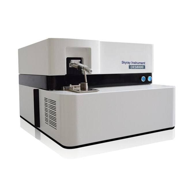
Optical emission spectrometers cover the analysis of the chemical elements at the complete range from sub-ppm to percentage levels from pure metals trace analysis to high alloyed grades. All relevant elements can directly be analyzed simultaneously.
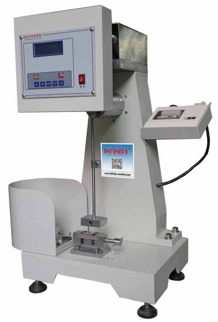
Impact test
An impact test is used to observe the mechanics that a material will exhibit when it experiences a shock loading that causes the specimen to immediately deform, fracture or rupture completely. To perform this test the sample is placed into a holding fixture with the geometry and orientation determined by the type of test that is used and then a known weight generally but not always in the shape of a pendulum is released from a known height so that it collides with the specimen with a sudden force. This collision between the weight and specimen generally results in the destruction of the specimen but the transfer of energy between the two is used to determine the fracture mechanics of the material.
Purpose of impact testing :
The purpose of an impact test is to determine the ability of the material to absorb energy during a collision. This energy may be used to determine the toughness, impact strength, fracture resistance, impact resistance or fracture resistance of the material depending on the test that was performed and the characteristic that is to be determined. These values are important for the selection of materials that will be used in applications that require the material to undergo very rapid loading processes such as in vehicular collisions.
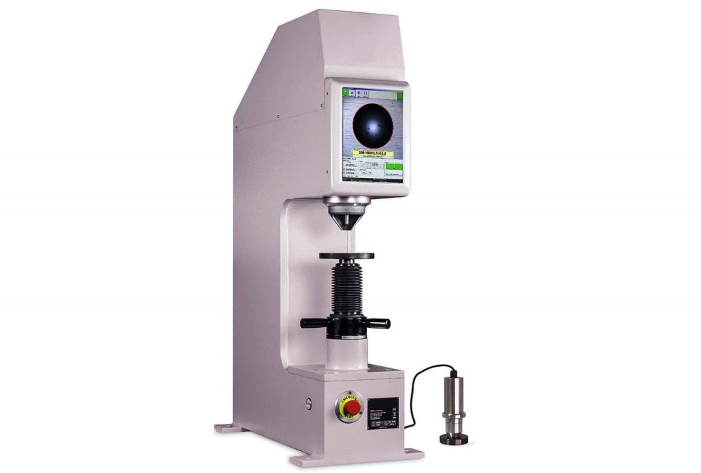
 Hardness test
Material Hardness Testing determines a material’s strength by measuring its resistance to penetration. Hardness test results can be extremely useful when selecting materials, because the reported hardness value indicates how easily the material can be machined and how well it will wear. Hardness testing of metals is routinely performed to assess the value of treatments and coatings
Testing is performed to ASTM specifications, as well as other standards and customer requirements for the type of material and application.
TEST METHODS/SPECIFICATIONS
• Rockwell – ASTM E18; NASM-1312-6
• Brinell – ASTM E10
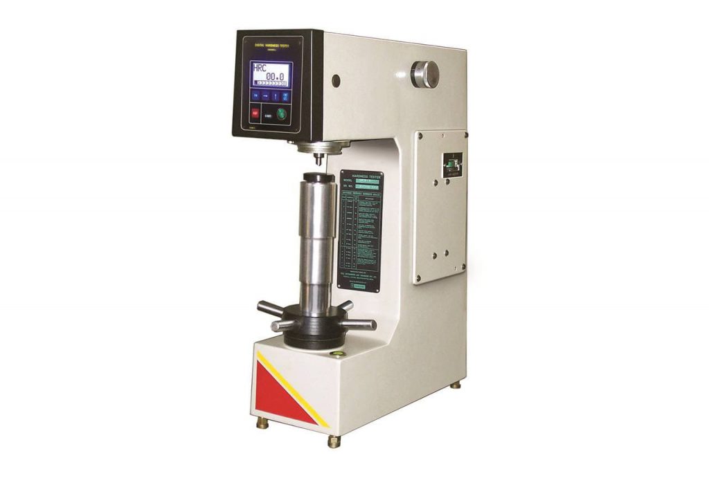
Rockwell Hardness test
In addition to a Rockwell Hardness Test, there is a Superficial Rockwell. For each test, a minor load is applied to either a diamond cone or a steel ball indenter positioned on the test material’s surface to establish a zero reference position. Next, a major load is applied for a specified amount of time, leaving the minor load applied upon release. The Rockwell hardness number will be the difference in depth between the zero reference position and the indent due to the major load
BrinellHardness test
During the Brinell Hardness Test, a carbide ball indenter is pressed into the sample with accurately controlled force for a specific amount of time. When removed, the material has a round indent that is measured to calculate material hardness according to a formula.
Tensile test
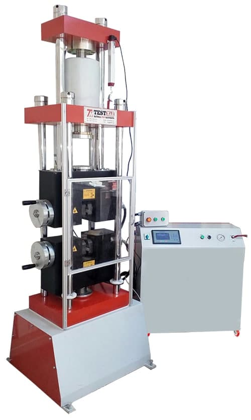
Electro-Hydraulic Universal Tensile Testing Machine
Universal Hydraulic tensile test machines are produced to test the ferrous materials for structural values such as yield strength and tensile strength. Universal test machines can also be used for compression tests up to the capacity of the machine. Maximum capacity is 600 kN. Can be test flat and round samples. 0-40 mm flat and 8-32 mm round samples can be tested with a hydraulic jaws that comply with standards.
Load cell is used for load measurements. Strain measurement is done by the electronic displacement transducer built in the machine if required external extensometer fitted to the specimen also can be used for strain measurement. Strain measurements can be done directly from the extensometer fitted to the specimen.
Tests can be done automatic by digital control unit or computer. Machine complete the test with the set pace rate and turns to start position automatically.
Data Acquisition & PC Software
The Universal Testing machine can be controlled (Start, Stop commands) by a computer with the software given free of charge by Testmak. This software provides data acquisition and management for compression, tensile and splitting tensile test throughout the test execution. The test results certificate includes all descriptive information. Therefore, test parameters can be set and details about the test carried out such as client details, test type, specimen type, user info can be printed out as well as test report and graph.
Roughness test
Why we measure roughness
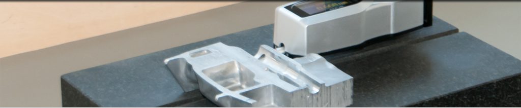
Surface roughness is an important parameter used to determine the suitability of a surface for a particular purpose. The irregularities on a machined surface impact the quality and performance of that surface and the performance of the end product. Rougher surfaces typically wear more quickly than smoother surfaces and are more vulnerable to corrosion and cracks, but they can also promote adhesion. A roughness tester, also referred to as roughness gauge or roughness meter, is a portable device that is used to quickly and easily measure the surface roughness (surface finish) of an object.
How we measure roughness
Typical roughness testers provide a linear roughness measurement, tracing a mechanical tip along a surface to measure roughness along an arbitrary line. More sophisticated versions provide an areal roughness measurement, which measures an area of the surface using non-contact methods, such as lasers, optics, interferometers, and more, to give finer resolution and wide area measurements. For this discussion we will focus on portable roughness testers and linear roughness measurement.
MPT testing
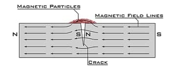
Magnetic Particle Testing (MPT), also referred to as Magnetic Particle Inspection, is a nondestructive examination (NDE) technique used to detect surface and slightly subsurface flaws in most ferromagnetic materials such as iron, nickel, and cobalt, and some of their alloys. Because it does not necessitate the degree of surface preparation required by other nondestructive test methods, conducting MPT is relatively fast and easy. This has made it one of the more commonly utilized NDE techniques
MPT is a fairly simple process with two variations: Wet Magnetic Particle Testing (WMPT) and Dry Magnetic Particle Testing (DMPT). In either one, the process begins by running a magnetic current through the component. Any cracks or defects in the material will interrupt the flow of current and will cause magnetism to spread out from them. This will create a “flux leakage field” at the site of the damage.
The second step involves spreading metal particles over the component. If there are any flaws on or near the surface, the flux leakage field will draw the particles to the damage site. This provides a visible indication of the approximate size and shape of the flaw.
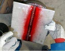
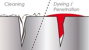
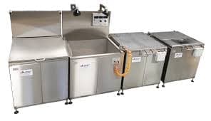
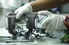 PT test
The basic principle of liquid penetrant testing (PT) is capillary action, which allows the penetrant to enter in the opening of the defect, remain there when the liquid is removed from the material surface, and then re-emerge on the surface on application of a developer, which has a capillary action similar to blotting paper. The term penetrant material includes all penetrants, solvents or cleaning agents that are used in this examination process. A penetrant material has the capacity to enter the crevices opening on the surface of a material. Fluorescent or visible penetrant with color contrast are used with one of the following three penetrant processes, namely, water washable, post-emulsifying, and solvent removable. The combination of fluorescent or visible penetrant with the three processes results in six possible liquid penetrant techniques. In the color contrast penetrant process, the developer forms a reasonably uniform white coating. The fluorescent penetrant process is similar to the color contrast process except that the examination is performed using ultraviolet light, which is also called black light
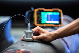
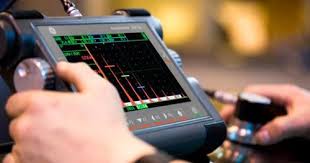
UT test equipment
Ultrasonic testing (UT) is a family of non-destructive testing techniques based on the propagation of ultrasonic waves in the object or material tested. In most common UT applications, very short ultrasonic pulse-waves with center frequencies ranging from 0.1-15 MHz, and occasionally up to 50 MHz, are transmitted into materials to detect internal flaws or to characterize materials. A common example is ultrasonic thickness measurement, which tests the thickness of the test object, for example, to monitor pipework corrosion.
Ultrasonic testing is often performed on steel and other metals and alloys, though it can also be used on concrete, wood and composites, albeit with less resolution. It is used in many industries including steel and aluminum construction, metallurgy, manufacturing, aerospace, automotive and other transportation sectors
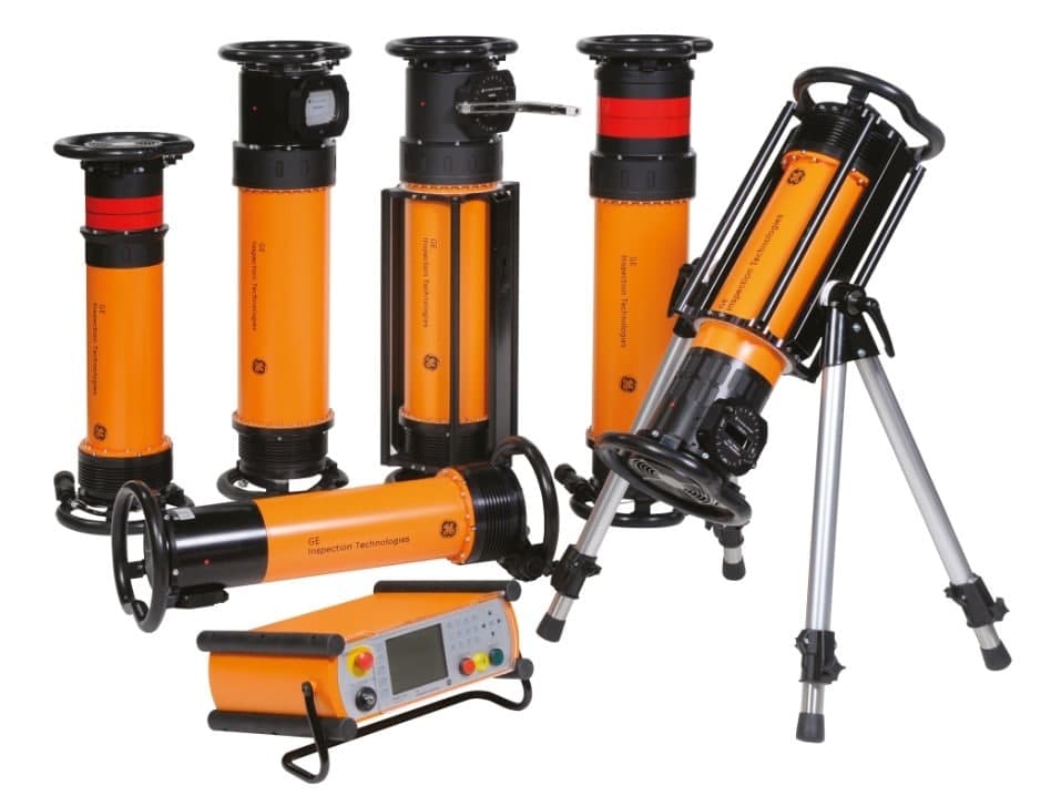
RT test
Radiographic Testing (RT) is a non-destructive testing (NDT) method which uses either x-rays or gamma rays to examine the internal structure of manufactured components identifying any flaws or defects.
X-ray or Gamma-ray source is required – whether it is an x-ray generator or gamma ray source via radioactive materials.
Recording medium – on the opposite side of the test subject needs to be a recording medium in order to capture the radiation and develop results for further analysis. Whether a film sheet is required or a digital detector panel, the images retrieved can be used to detect defects and failures. Although film radiography is not obsolete for industrial applications, it is steadily being replaced by computed radiography (CR) and digital radiography (DR).
Processing Equipment – If the technique of analyzing part is film radiography, processing equipment such as chemicals are necessary to develop the image. For digital radiography or computed radiography, processing equipment such as scanners, computers and specialized software is necessary to develop, restructure and analyze the resulting image
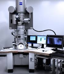
Electronic Microscope
An electron microscope is a microscpoe that uses a beam of accelerated electrons as a source of illumination. As the wavelength of an electron can be up to 100,000 times shorter than that of visible light photons, electron microscopes have a higher resolving power than light microscopes and can reveal the structure of smaller objects.